Description
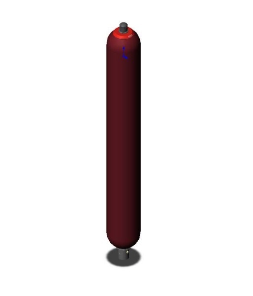
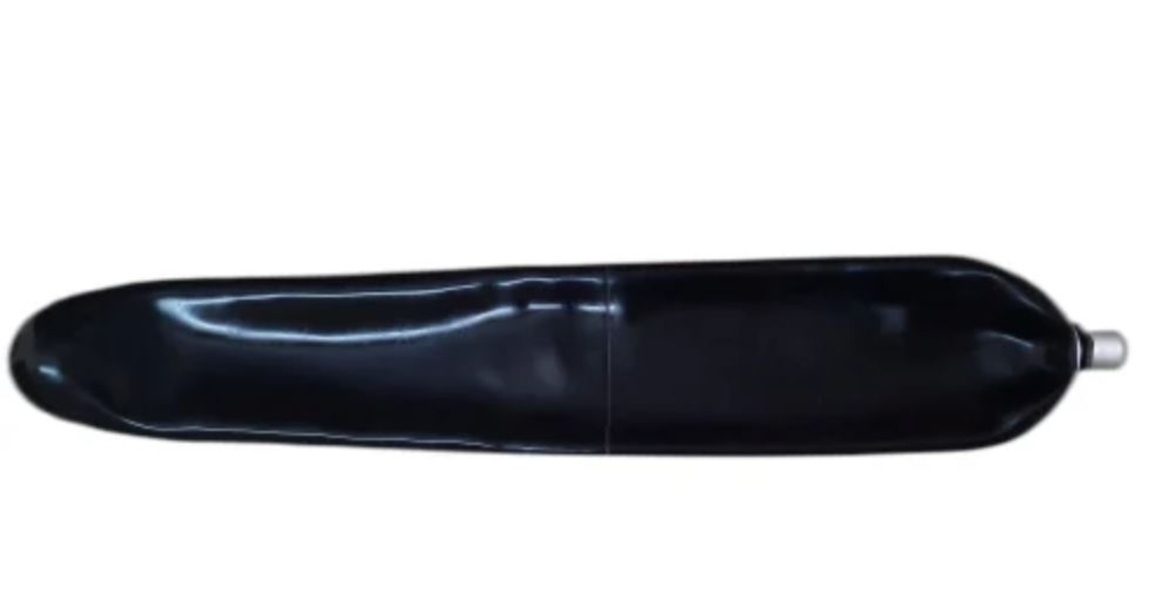
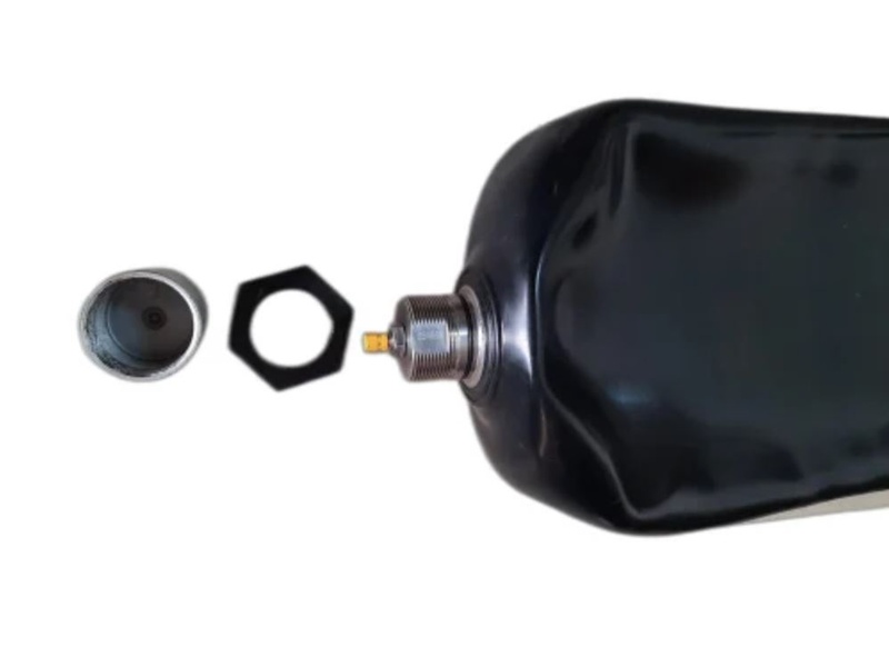
Hydraulic accumulators or pressurized hydraulic containers. Accumulators of this type consist of a seamless cylindrical pressure vessel made of high-strength steel. An elastic bag mounted inside the container divides the accumulator into its gas and liquid sides. The bag is filled with nitrogen to the specified gas filling pressure P0 using a gas valve. When the fluid is forced into the accumulation, the gas in the bladder is compressed, increasing the pressure. The gas volume is reduced, and on the liquid side, the liquid can flow from the accumulation. As soon as the pressure on the liquid side drops below the gas pressure, the accumulation is discharged. The oil valve is located in the oil port of the bag accumulator and closes when the pressure on the gas side is higher than the pressure on the liquid side. This prevents the bag from draining into the oil channel and thus destroying it. When the minimum operating pressure is reached, a small volume of oil must be maintained between the bag and the liquid volume (approx. 10% of the nominal capacity of the hydraulic accumulator) so that the bag does not hit the valve during each expansion process. The gas valve consists of outer caps, sealing cap, filling valve, gas valve body, and rubber washer. These parts can be replaced separately. The technical data and properties of the hydraulic accumulator are listed on the nameplate.
SB 330 – 50 A 1 / 112 U – 330 B
B = thread to DIN13 or ISO965/1 (metric)
| Fluid port, flange | Without flange, but thread |
|---|---|
| Nominal volume | 50 |
| Series | 330 |
| Pre-charge pressure adjustable | Yes |
| Material Bladder | NBR |
| Material Accumulator shell | Carbon steel |
| Material: fluid port | Carbon steel |
| Preferred models | Yes |
| ATEX | No |
| Suppl. equipment, fluid-side | No additional equipment |
| Back-up version | No |

Reviews
There are no reviews yet.